|
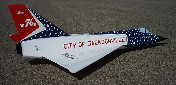
Convair
F-106 Delta Dart |
 |
|
Convair
F-106 Delta Dart |
|
| Middle Fuselage & Inlet Construction | |
 |
 |
|
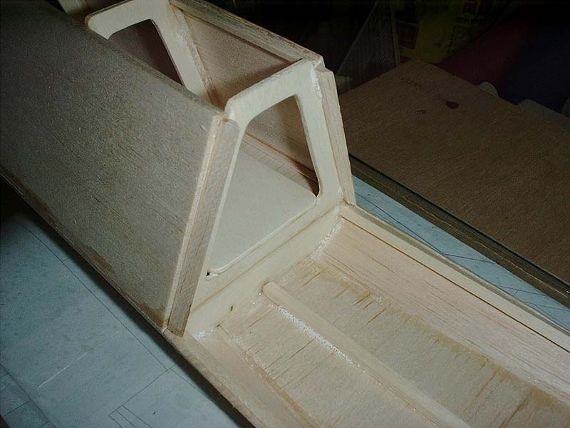
Position and align the forward fuselage over the plans making sure that the cross-grain fuslage bottom FB2 overlaps onto the bottom of bulkhead B6B. Tack glue the fuselage bottom to B6B. cut a short length of 1/4" balsa triangle stock and glue into place along the joint between B6B and the fuselage bottom sheeting. Cut two pieces of 1/4" balsa square strip stock to length so that they will fit between B6B and B7. Position and glue each piece so that it will act as the base for the sheeting that will fair the curved bottom corner of the forward fuselage to the beveled bottom corner of the rear fuselage. They will have to be twisted slightly so that the outer face will align with the portion of the fuselage to which it is mated. |
Using 3/32" contest sheeting, make the sheeting pieces that will fair the curved bottom of the forward fuselage to the beveled bottom corner of the rear fuselage. Make this sheeting pieces so that they will be even with the top of the 1/4" strip stock when they're glued into place. Wet the outside of the front have of the bottom sheeting pieces and glue into place. Cut a pieces of 1/4" balsa strip stock and glue it along the centerline of the cross-grain balsa fuselage bottom. Once the bottom fairing pieces have dried, bevel the outside top corner so that the side filler pieces will form a lap joint with the bottom corner sheeting you just glued into place. |
 |
 |
|
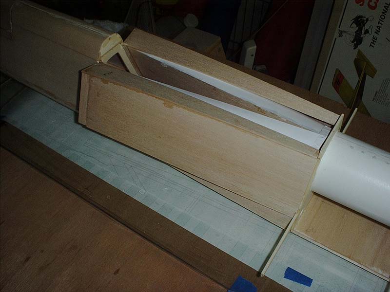
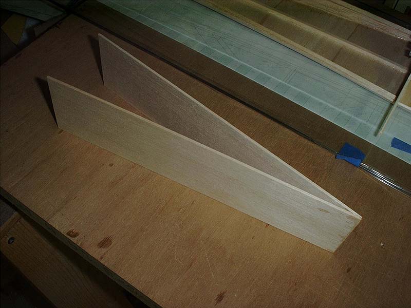
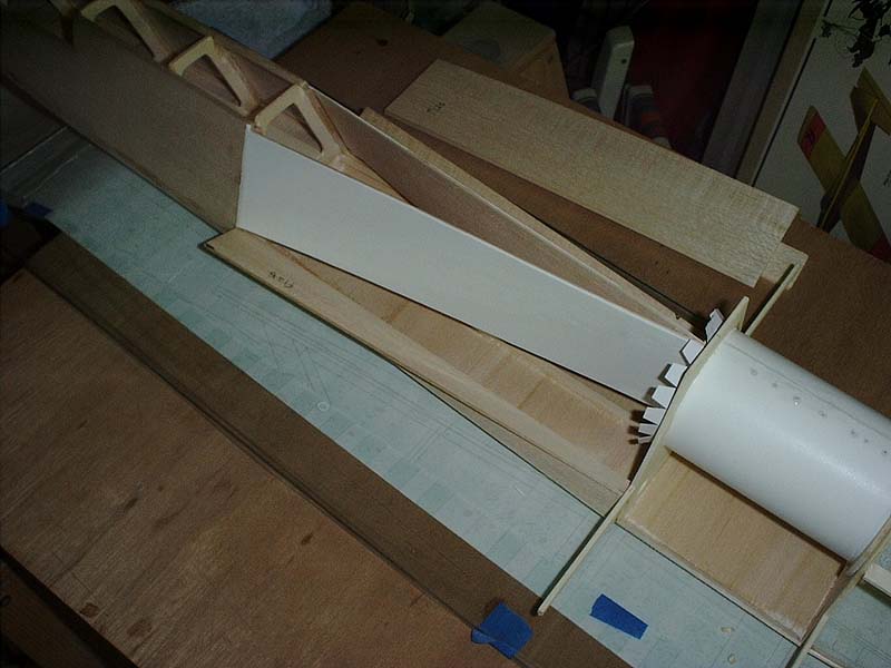
Cut two pieces of 1/4" balsa triangle stock so that they will fit into place along the outer edge of B6T. These will act as the base for the inner inlet duct walls, so bevel these so that the out faces are angled back to the centerine of the model at bulkhead B7. Position these 3/32" inboard from the outer fuselage side. This will ensure that the FI1 inboard inlet duct walls will be flush with the outside of the forward fuselage side. |
Bevel the trailing edge of the FI1 inboard inlet duct walls so the forward edges will match up with the rear of the forward fuselage section. Make sure that the rear joint is 3/32" thick when complete. Once the bevel is correct, stand both FI1 inlet duct walls up on the building board and tack glue the rear joint together. Remove from the building board once the glue has dried and reinforce the joint with a bead of glue. |
 |
 |
|
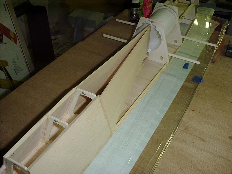
(Ed. Note: This would be a good time to construct and install the plywood battery box and mount that will fit between B6, the inboard inlet walls and the bottom sheeting of the fuselage. Details to follow.) When the glue joint is dry, position the FI1 inboard inlet duct wall assembly into place between the rear duct splitter plate and the outer edge of bulkhead B6. If the angle of the 1/4" triangle stock isn't correct, remove the inboard duct walls and sand the triangle stock until it is correct. Once the fit is satisfactory, glue the FI1 inboard inlet duct wall assembly to the 1/4" triangle stock, the forward fuselage sheeting and the rear duct splitter plate. |
Using white Monokote or equivilent, cover the outer surfaces of the inboard inlet duct walls. Make sure to overlap the glue joint between the inboard inlet duct wall and the rear duct splitter plate. Do not cover the top or bottom of the inboard inlet duct walls. The paper inlet ducts will be glued to these and Monokote would weaken the glue joint. |
 |
 |
|
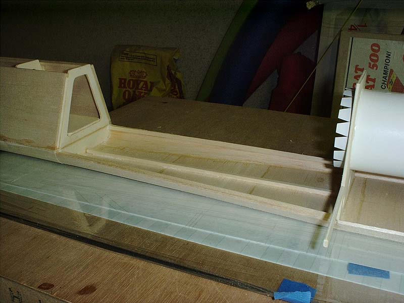
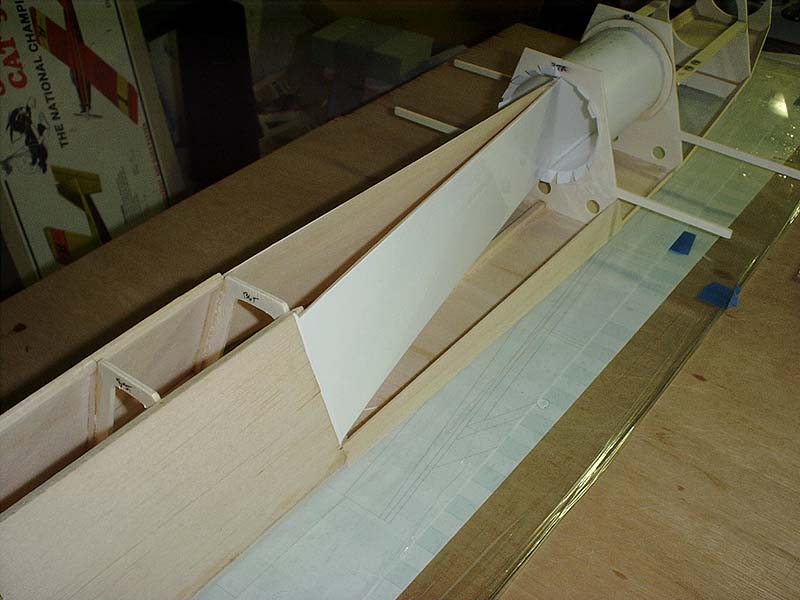
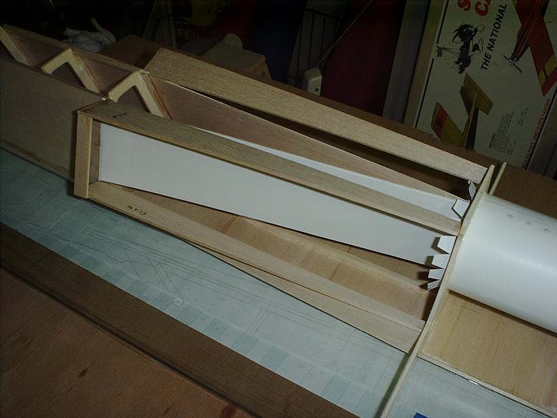
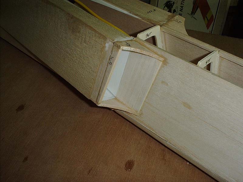
Using 3/32" contest balsa sheeting, make the lower fuselage side filler pieces that go between the lower curved/beveled corners and the bottom of the inlet duct pieces. Be sure to leave a 1/8" gap between the top of these filler pieces and the lower edge of the inboard inlet duct wall. Fit the 3/32" balsa bottom inlet piece, FI2B to the top of the filler piece and to bulkheads B6T and B7. Be sure to leave 1/32" gap between the top of FI2B and the inboard inlet duct wall. This gap is necessary because the outer inlet duct will be glued to the bottom of the inboard inlet duct wall. If you glue FI2B so that it is in contact with the inboard inlet duct wall, then the outer inlet duct will not fit properly. Make sure that FI2B is perpendicular to the side of bulkhead B6T. Once FI2B has been fitted, glue to the bottom filler piece and to bulkheads B6T and B7. |
Fit the 3/32" balsa top inlet piece, FI2T. Leave 1/32" gap between the top of the inboard inlet duct wall and the inside (bottom) of FI2T. The outer inlet duct will be glued to the top of the inboard inlet duct wall. Make sure that the inboard edge of FI2T does not descend below the top of the inboard duct wall. Use the 3/32" balsa outer duct sheeting piece, FI2S to locate the FI2T in the proper place on bulkheads B6T and B7. It will be necessary to cut a 1/16" notch into the trailing edge of FI2S so that it will fit into position around the forward wing stub spar that is a part of bulkhead B7. |
 |
 |
|
Note that the angle of FI2T is slightly different than FI2B. Once FI2T is in the proper place and at the proper angle, glue to bulkheads B6T and B7. Cut a 3/32" X 1/2" piece of balsa that will be used as a filler piece between the leading edge of FI2T and FI2B. This will help support these while you're fitting and gluing the outer inlet duct. |
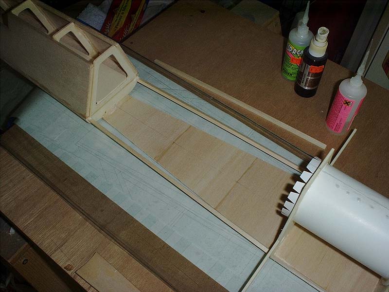
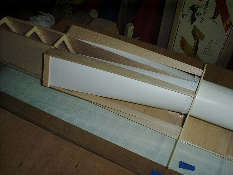
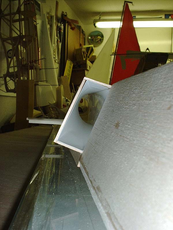
Cut the right and left outer inlet duct out of 100# Bristol paper. Fold the creases where indicated on the plans. Do not make a crease along the entire length of the outer inlet duct. It should change naturally from a rectangular shape to a round shape. Slip the forward part of the outer inlet duct into the rear portion of the forward inlet opening, insert the rear portion into the fuselage, then slide the paper duct rearward into place inside the tabs you cut earlier into the rear inlet duct. Trim as necessary to get a good fit between the inboard inlet duct, the rear ducting and the forward inlet opening. Take your time and you should be rewarded with nicely shaped inlet. Be sure to fit both sides before gluing either into place. Doing this will allow you to make sure both sides fit properly. Once you're satisfied with the fit of the outer inlet duct on both sides, tack glue the outer duct where it contacts the inboard inlet duct wall. Make sure that it stays flat with no wrinkles. Next glue the outer duct to the top of the inboard inlet duct wall. When this is done, carefully glue the tabs of rear inlet duct to the outer inlet duct. Lastly, glue the outer inlet duct to the inlet tops, FI2T, bottom, FI2B and the 3/32" X 1/2" filler piece. Repeat for the other side. |
 |
|
|
Because the length of the paper inlet is unsupported by any structure, the square portion will be subject to mild oil-canning or flexing. To prevent this flexing, you'll want to reinforce this area with another piece of 100# Bristol paper. Cut two pieces of 100# Bristol paper that are 2" X 5" Carefully curl the back half of these so that it will naturally form to the shape of the outer inlet duct. Each one of these reinforcements will be glued to the outside wall of the outer inlet duct. The front of the reinforcement will be located 1/2" aft of the 3/32" X 1/2" fill piece. When the paper reinforcements are formed, working on one side at a time, spray them with two coats of 3M 77 or equivalent spray glue. While the glue is still slightly gooey, position into place on the outside of the outer inlet duct and gently rub it down. Be careful not to deform the outer inlet duct. Keep rubbing it down until the edges and corners no longer want to pull away from the outer inlet duct. Repeat for the other side. |
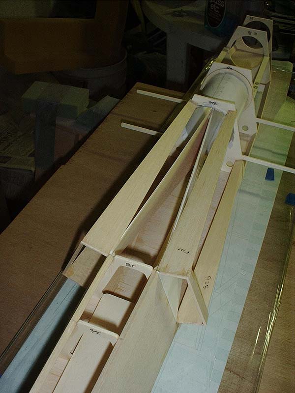
Finish the basic construction of the inlet duct area by gluing the 3/32" balsa inlet outer sides, FI2S pieces. These should fit flush with the top and bottom of the top inlet pieces, FI2T and the bottom inlet pieces, FI2B. Be sure to leave a 1/16" lip on the outer edge of bulkhead B7. The rear fuselage sheeting will be glued to this lip.
|
 |
 |
|
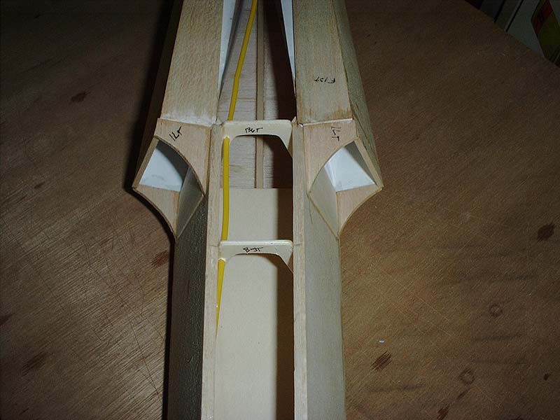
The final step to complete the construction of the middle fuselage and inlet ducts is the addition of the 1/16" and 1/8" balsa inlet lip pieces. Position and glue the inlet lip top, ILT and inlet lip bottom, ILB so that the inner face is flush with the surface of the inlet ducting. Make sure that the ILT and ILB follow the lines of the inlet area. Any excess should be outside where it can be easily sanded away. |
Once these are glued into place, position and glue the outer inlet lip ILO. Lastly, fit the 1/16" balsa splitter plate between ILT and ILB, but don't glue it in place, yet. Once you've got a good fit, remove the splitter plate and sand the trailing edge so that it fairs smoothly into the inboard inlet duct wall. Also, round the leading edge. Once this is done for both sides, glue the splitter plate into place. This completes the inlet construction. |
|
Construction of the middle fuselage and inlet area took about 5 hours. To finish the fuselage, return to the rear fuselage area to add the rear fuselage sheeting. |
|
| Forward
Fuselage | Rear Fuselage
| Middle Fuselage & Inlets Home | Wings | Fuselage | Fan | Servos | Final Assembly | Covering | Finish | Components | Flight | Gallery |
|